EFI conversion for the 110 (part 1)
24/03/08
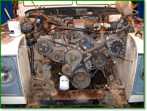
Well it had to come sooner or later, the 110 has over 200k miles on the clock and the engine was getting tired. Depending on how they’ve been looked after, they reckon a Rover V8 will be getting tired by 50k to 100k miles - so this one wasn’t doing too badly.
I scrapped a Discovery last year, specifically for the engine and axles, so the engine out of that was overhauled ready to pop in the 110. Now simply swapping the engine on a ‘like for like’ basis is fairly simple, possible in just a day, but swapping in an efi engine where once were carbs is a different matter. For the benefit of anyone else considering such a change, here is what I’ve found out.
Firstly, I’m told that all the V8 blocks are identical externally - even down to still having imperial threads in the latest 4.6 models. So you can take a 4.6 block and bolts on the font cover and ancillaries from a 3.5 and it will all fit (you need a spacer between crank pulley and retaining bolt as the crank has a longer nose on the 4.6) - something I have in mind when funds permit (there’s a 4.6 sat in the garage waiting !) If you are replacing a diesel then there’s more changes as I believe the engine mountings on the chassis need changing (but that’s not something I’ve done ... yet - I have a diesel 90, and a spare V8, hmm), and of course you’ll need a suitable gearbox or adapter. In this case it was already V8 so that is taken care of.
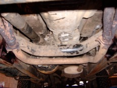
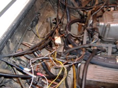
There are two lots of electrics to deal with - the engine loom and the efi loom.
I used the Disco engine loom, so it’s mostly a matter of cutting off the round plug, removing the wires not needed (brake fluid level switch) from the loom, then soldering on some bullet connectors. You’ll also need an extra cable with a ring terminal one end (battery connection on starter) and two bullets on the other end to feed the main harness - this is part of the engine harness on the 90/110 harness, but not on a Disco where the feeds all come off a stud in the bulkhead. Also, on the Disco the feed for the coil is via the loom on the nearside wing, so I used the wire originally intended for the tacho (‘W’ terminal on the alternator) instead. Having connected everything up you should then have a vehicle with electrics, oil and alternator warning lights, starter - but no fuel. I’l add that I haven’t done all the electrics yet - just enough to be able to drive it home.
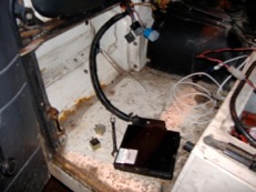
I’m fitting the ECU and relays in the passenger footwell - above the piece of cardboard that’s normally there. Before putting the new engine in, I used a holesaw to cut a hole and feed in the efi harness. It’s not all the way through in these pictures as it needs further modification - the wires to the idle stepper motor need extending as the loom was originally intended to go through on the drivers side. At the moment they are simply sat on the floor as shown. While I was rebuilding the engine, I took the opportunity to modify the efi harness for the LPG conversion - adding a relay and extra connector. On these injection systems you can cut the petrol by removing the supply to the injectors themselves and avoid the cost and wiring complexity of eight cylinders worth of emulators - this is fairly easy to do with just one relay to interrupt the brown/yellow wires going up the harness to the injectors, but note that one of these also feeds the supply to the air flow meter so part of the harness needs untaping to bring a separate wire down to the live side of the relay.
In the next part, I’ll show where I moved the LPG reducer to, what I did with the washer bottle, and how I mounted the air flow meter and filter.


