Hacking the EFI Loom
30/03/08
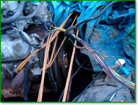
In my last entry, I mentioned having modified the efi loom to make life easier for the LPG conversion - in this article I’ll detail what I’ve done and why. Note: this is only for early(ish) efi systems (flapper and 14CUX hotwire), I won’t be touching on later systems like the Thor.
First, what do we need, electrics wise, when fitting an LPG conversion ?
Well that depends, mostly on the type of system being fitted, but for the most part I’ll assume a closed loop system with an electronic controller and lambda probe. The details vary but in general all of them will require a basic set of connections from the host vehicle - permanent and switched power supplies, ignition pulses, throttle pot. In addition, they will all need a means of turning off the petrol, and this is where you can help yourself here.
The common way of turning off the petrol is to disconnect the injectors from the ECU, and this is normally done with one (or in the case of a V8, two) injector emulator. An injector emulator is really nothing more than a relay that electrically disconnects the injector, and you normally get several in one box. You can get these with ‘open end’ wires that you solder into the host system, but more commonly they come with a plug and socket for each injector - you pull the lead off the injector and connect it to the emulator loom, and connect the other connector on the emulator loom to the injector. Conveniently, with the early Land Rover systems there is a neater and cheaper option which I detail here.
Simply put, we’ll simply disconnect the power supply to the injectors ! On these basic systems it doesn’t do any harm at all, and it can be done with just one relay. If your vehicle has lambda probes, see the note at the end before starting !

So lets start at the engine end of the loom and work back.
Where the left hand injector bank and air flow meter branches join together, untape the harness and work back towards the ECU. What you will find varies depending on the system.
On the flapper system used on early 3.5s, there are two brown/orange wires that go to a resistor block on a bracket to the left of the engine plus one to the air flow meter.
On the 3.5 loom from a 91 Disco you will find five small brown/orange wires (four from the injectors, one from the air flow meter) that go into a soldered joint.
On the 3.9 loom from a 92 Range Rover, there are two brown/orange wires - one large and one smaller. The larger one goes to the left hand injector bank, the small one to the air flow meter.
The basic principal is that we need to leave the supply intact to the air flow meter, while cutting the feed to the injectors, and obviously this varies by system.

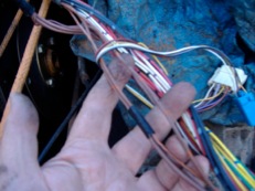
On the 3.5 hotwire loom we cut the one coming from the air flow meter, and solder a piece of wire to it - this needs to be long enough to reach the main relay. Having insulated the cut end and the soldered joint, we can continue untaping the loom, and temporarily taping the loom back together with the extra wire in it.

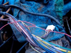
We now continue untaping, and temporarily taping the harness back together with the two extra wires until we reach the branch for the relays.
We need to cut the large brown/orange wire that comes out of the main relay and feeds the injectors, while connecting anything we split off further up the loom. We connect two pieces of thick wire (brown/orange if you have it) to the two ends, and together with the extra yellow wire we added, form a new relay bundle.
Now, we connect the new feed to the injectors to terminal 87 of a new relay base, the feed from the main relay to terminal 30 plus (using a smaller wire) terminal 85, the yellow wire goes to terminal 86.
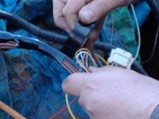
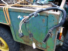
Returning to our bundle of new wires near the main harness connector, we can now fit a new socket and plug. it would be easy to just fit one socket, but here’s a trick - we connect the yellow wire to it’s own plug so that we can unplug the LPG system and the petrol system will work as though we hadn’t touched anything !
The trick is that if we make the yellow wire connect to the black wire when we put this plug and socket together, our extra relay will alway be closed whenever the efi system is powered up.
We put the brown, white, white/black, red, and black wires into a socket. We put the yellow wire into a matching plug so that if the two are put together, the yellow wire is connected to the black.


If this is an issue for you, or if you have any comments, then please let me know and I’ll look into it. Otherwise I’ll look into it when I have the need !
Update: A reader contacted me to say that disconnecting the power to the injectors like this will bring on the MIL (Malfunction Indicator Lamp). It doesn’t on the old ‘flapper’ systems, but on the newer systems I can see a solution by using a changeover relay, two diodes, and two resistors. Add the diodes and resistors so that when the fuel cutoff relay we’ve added is off, the normally closed contact supplies a small current through them to the two injector bank circuits that go back to the ECU. The ECU will then see a voltage there and should be happy.
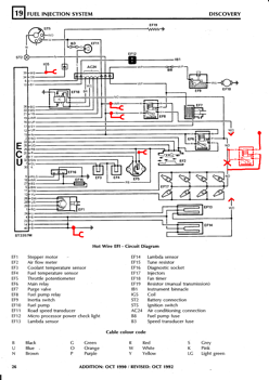
Here I have a wiring diagram for the Discovery 3.5 EFi system - with the modifications marked in red (click for larger image). The extra mod mentioned in the update is to connect a pair or resistors (with blocking diodes) from the normally closed contact (not shown on our extra relay) to the YW and YU wires - the negative switched injector bank connections.
NB: The two arrowheads on the WO lines are simply where I’ve broken the line to make the diagram easier to modify. You don’t cut the WO wire.


