


I’m in pieces … or rather this valve is
30/12/12
(Click for larger version)
We changed a multivalve on my friends Range Rover a while ago, one of his tanks wasn't opening the outlet valve and so he was carting a tankful of unusable gas about. We dropped the cradle, took the tank off, and hooked up 12V to the solenoid - nothing happened. A ‘light tap’ on the solenoid brought forth a jet of gas, so we concluded the valve was sticking. After closing it and reapplying power, the same thing - nothing till we tapped it.
WARNING - be very careful with this technique, you are letting out flammable gas, and then making sparks connecting 12V to the solenoid (and also when disconnecting). Do I really have to spell out what flammable gas mixture plus sparks can do ?
Now we could have tried dismantling the solenoid bit of the multivalve, but realistically there's not a lot you can do to fix it. So we pumped out all the gas we could, using my hand pump to transfer it to the other tank, and then removed the multivalve. Now this is the first time I've done this, so it was a new experience being able to look into the hole and see the remaining gas bubbling away in the bottom of the tank. I‘m guessing it was ‘quite cold’, something backed up by the thick layer of white frost round the bottom of the tank.
So new multivalve fitted, everything put back together, and the tanks refitted in the vehicle.
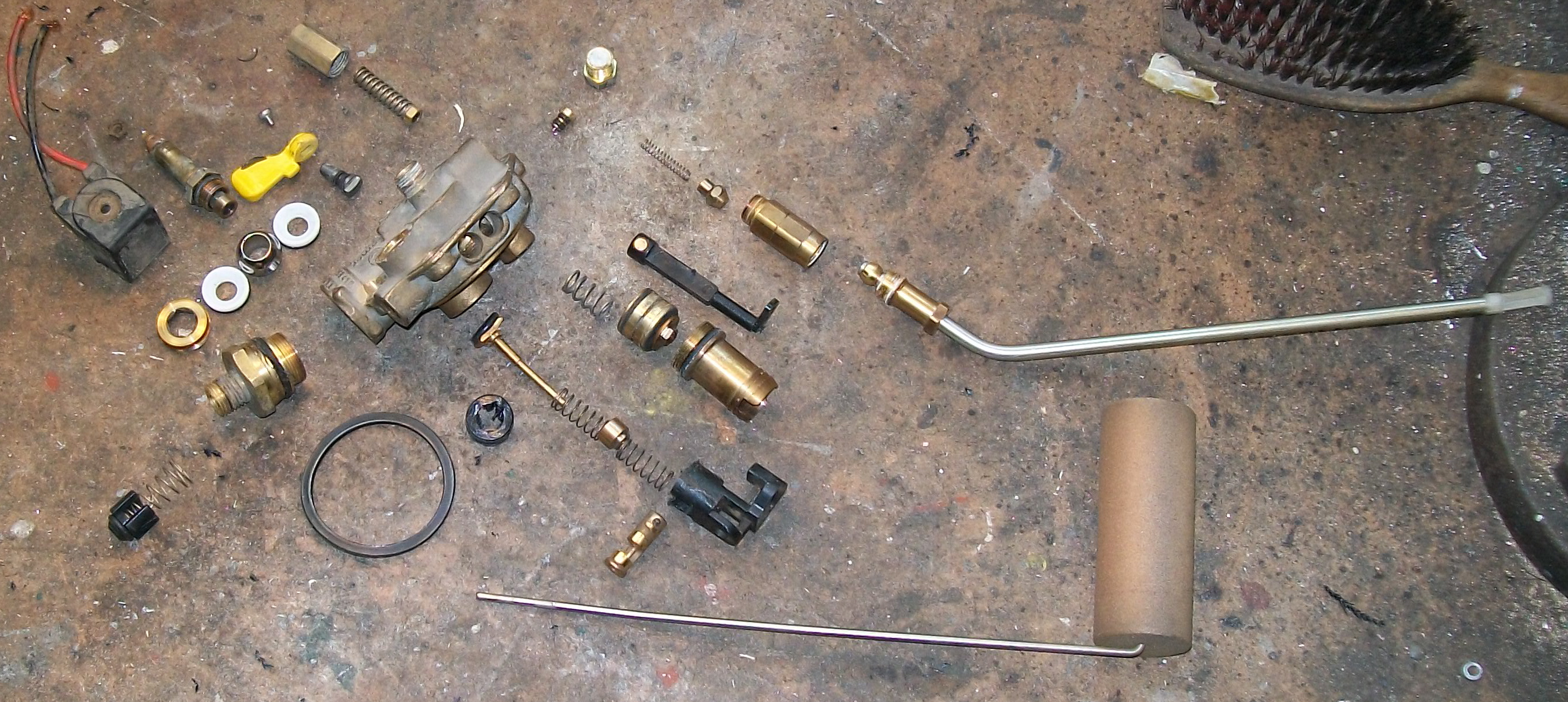
Anyway, being curious I decided to take the old valve apart and see what's in it. This is what I found - what a lot of bits !
The body is easy to see - it’s the large brass bit towards the upper left of the photo.
To the left of that are the internals for the manual shutoff and solenoid valves. Below them the inlet and it’s non-return valve. And at the top, the first stage of the pressure relief valve.
Top centre is the fusible plug.
To the right, from top to bottom are the pick up tube and it’s combined excess flow shutoff and non-return valve; the internal part of the level indicator (there’s a magnet in the top-left end of the plastic shaft); the second stage of the pressure relief valve; fill point with high level shutoff; and finally the float arm.
Perhaps this might be a good time to describe some of the safety features that you may or may not be aware of – because there is a lot packed into that little valve block.
The first, and most obvious is the high level shutoff. If the valve and tank are installed correctly, then this will shutoff the flow during filling once the tank gets to around 80% full. This leaves a good space for the liquid to expand into if the temperature rises.
The next bit I think most people will be familiar with is the pressure relief valve – the first stage of which is top left in the photo. Simple enough, if the pressure gets too high, it lifts the plunger off it’s seat and allows gas to escape. From memory, this has a second stage which is shared with the fusible plug - and that’s the large plunger and barrel roughly in the middle of the photo.
This large plunger is normally held in place with a spring, and it has a small hole through it that allows the pressure to equalise across it. If there is enough flow through it, then the pressure difference will be enough to make it move – when it does move, it will uncover large ports around it’s side (normally sealed between the two O-rings) which allow a massive flow rate. The required flow rate can be because of excess pressure opening the relief valve, or excess temperature operating the fusible plug.
Having mentioned it, this is the third bit of protection. If the vehicle is on fire, the temperature can get very high – and with it the internal pressure. In principal, the pressure relief valve should take care of allowing gas to escape and control the pressure. There is a risk that if the tank gets hot enough, the steel will start to lose it’s strength and the tank will rupture – releasing whatever is left of it’s contents explosively. This fusible plug takes care of that by melting – it has a core of metal with a melting point well below the temperature at which there is a risk of the tank rupturing. Once it does so, it lets the gas out (using the second stage “servo” valve already mentioned) at a rapid rate. Once this is triggered, it’s non-reversible – the tank contents will pour out until the tank is empty.
Bear in mind that automotive tanks are generally fairly small – so it’s unlikely that part of the tank will get hot enough to soften and rupture while there is still liquid boiling off (which takes energy, and hence heat) to do.
To finish with, here’s a video of a small automotive tank subject to a fire test. Notice how it lets all the liquid boil off safely – which is a certification requirement for the valve sets.
And here’s a video of a larger tank, where the heat is deliberately aimed at a small portion so as to cause a failure (come on now, everyone likes “blowing stuff up”), demonstrating what’s known as a BLEVE (Boiling Liquid Expanding Vapour Explosion). Once the tank ruptures, the pressure drops, so the remaining liquid is now superheated – it’s well above it’s boiling point at atmospheric pressure. As a result, it flash boils, creating huge volumes of vapour. This isn’t restricted to explosive/combustible gasses – I’ve personally witnessed it happen with the cooling system on a rally car, and it was “impressive” to say the least, as well as being quite destructive.