


Installation Rules and Bits Part 1
31/05/08
The other day well I was filling up, someone was using the pump on the other side of the dispenser, and as I tried to make conversation over the top of the unit, he mentioned that he was disappointed to have got his conversion back with a spare wheel well donut - and that he intended adding a cylinder in the boot. “It just bolts in” he said.
His tank was now full and that was that, but I wonder what he meant by “it just bolts in” ?
So I thought I’d start covering some of the details in these articles, which no doubt will go down like a lead ballon with those installers that would prefer it to remain a black art that only they can practice !
And just to remind you (you did read the previous article on legalities didn’t you !), parts used should be to ECE R67.01 - I’m not going to mention this right through the article. Also, I’m not going to cover everything here so this isn’t sufficient on it’s own - if you are going to fit your own conversion (or parts) then seek advice from someone who is qualified. But this should give you a good idea of what’s needed.

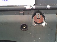
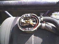
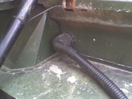
For use in the UK, you should ideally have a bayonet fitting, but many use a screw fitting and supply an adapter. I had a screw fitting on my old Disco (it’s just visible on the rear side panel near the petrol filler in these pics), and whilst it has the advantage of significantly reduced dimensions, it has the disadvantage of having to screw in the adapter every time you fill up - and occasionally the pump jocky would tighten it with the pump nozzle while fitting it and make it impossible to remove by hand. Make sure that if you do have a bayonet fitting, that it also has an internal thread - that way you will be able to use adapters should you need to (such as when abroad).
Hint: if you don’t get the pins on the bayonet fitting horizontal (ie at 9 and 3 o’clock) then it makes it hard to use with some dispenser nozzles. GasGaurd ones are awkward, but DeVisser aren’t too bad.
Pipework. Depending on your tanks, then you could have two different types of filler pipe. “Multivalve” (or “1 hole”) tanks usually use 8mm copper pipe, “4 Hole” tanks usually use reinforced flexible pipe with JIS fittings crimped on (ie just like the hydraulic pressure hoses you see on agricultural machinery). While you can get converters from one to the other, it’s simplest to just stick with what your tank requires and get a filler to suit.


Do not use any more joints than are necessary for the fittings & equipment used, joints should be flared or compression joints with a brass olive.
For a copper fill pipe, 8mm is normally used. 6mm is normally used for the supply pipe, but in high demand applications (ie several hundred horsepower) either two 6mm pipes (from two tanks) or an 8mm pipe is used.

Part of the course involved a walk round the warehouse to see the range of items available - the smallest is about 6l (to fit in the helmet box of a scooter !), and they go all the way up to 200l and above. This is usually the hardest part of any conversion, deciding on the ‘right’ compromise between cost, space, weight, and capacity of the tank(s). As you might have seen from some of the pictures on this site, older Land Rovers (and other large vehicles like them) have some useful options for tanks underneath, but in the case of most cars (and newer Land Rovers where there are all sorts of bits such as air suspension compressors stuck underneath) you are more limited and it can often come down to “spare wheel well” or “cylinder in the boot”.
Cost wise, cylinders are the cheapest by quite a margin, followed by open toroidal, closed toroidal, and specialist tanks. Single hole tanks, and the valves for them, are generally slightly cheaper than 4 hole tanks and valves.
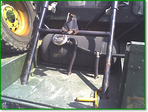
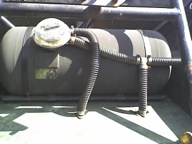
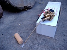
When considering the space available, don’t forget to allow for the valves and pipework. Cylinders have the valve on the outside as in the photos above - you can get an idea of the size as the tank is 80l capacity, 360mm diameter, and 892mm long. On a 4 hole tank, the optional valve box will approximately make up a square corner on a 360mm dia tank - ie if you were to draw a 360mm circle in a 360mm square, the valve box would fill one of the corner spaces.
On an open toroidal, the valve is inside the hole in the middle, so the quoted size of the tank is all you need. On a filled centre toroidal, the valve sticks out quite a way on one side (it’s not actually visible in these pictures, but it’s between the tank and the towbar on my 110).
Once you’ve chosen your tanks, it’s time to mount them. You have several options available and it largely depends on what your requirements are.
For a “cylinder in the boot” job with the tank mounted across the vehicle, the simplest method may be to use the manufacturers mounting frame (as in the top picture above) - you just bolt it down with 4 to 8 bolts (as specified in the manufacturers instructions) and large washers or spreader plates underneath, strap the tank to it, and that’s it. The manufacturer has taken care of the calculations and you can be reasonably confident that it’s going to stay put. I have seen the frame welded in, but that was in a Range Rover with an aluminium floor - so although there were numerous beads of very neat welding, only the one in the extreme corner (where the floor is steel) was actually attached to anything, so I don’t think that was going to take 20G !
If the floor isn’t flat enough for that, you can use “cheat bars” which are telescopic bars with a mounting flange on each end. Just bolt them in between the wheel arches or whatever structure is in there, and strap the tank to them.
Open toroidal tanks are even easier to fit - drop it in the spare wheel well and drill three holes (two for bolts, a bigger one for pipes and cables). Once the pipes and cables are connected, a cover screws down on the top of the centre hole and closes that off from the inside of the car. The large hole with the pipes and cables also serves as the vent. Advice on the course was “if you can’t fit one of those in 20 minutes you’re slacking !”
Other tanks frequently have preferred mounting methods - for example the 66l toroidal under the back of my 110 has mounting brackets on the top, and mounting frames are available for other toroidal tanks.
For underslung tanks you can use brackets or straps, on my 110 I’ve welded substantial brackets to the chassis for the 36l cylinder under the drivers side. If you use brackets then you need two, if you use straps then you need three (to allow for one of them getting damaged). Unless the tank is physically protected, it should not be lower than either the original load bearing structure or 200mm (8 inch).
I’ll finish up with a few more loose ends on tank mounting :
Tanks should be mounted to withstand 20G acceleration in the direction of travel, and 8G horizontally at right angles to direction of travel. 20G is quite a large factor, it means that the mounting is expected to withstand a force 20 times the weight of the tank, or well over a ton for the tank in the pictures above ! It’s commonsense really, but you don’t want the tank coming loose in an accident.
Straps, brackets, cradles etc should have plastic or rubber protection to prevent fretting and corrosion of the tank - the straps supplied with Stako cradles are plastic coated to take care of this. There is a specified standard for straps, but yet again, either just use ones sold for the purpose or read up and get the full spec.
Tanks should be protected from impact, and should not be outside the plan of the vehicle unless protected.
You can mount them on the roof, there are specific rules for it. However, I would not in general recommend it because of the weight.
Next time I’ll move forwards and cover the stuff under the bonnet.